RFID projects, 2021
Before Purdue
A motorcycle lock that opens for an RFID chip implanted in its owner's hand, and a 13.56 MHz card reader and writer. At least seven prototypes got the lock onto the motorcycle.
The problem
I built two RFID devices. An RFID tag carries an ID that a reader picks up by radio, without contact.
The first was a personal project, unpaid, for a rider who wanted his motorcycle, a SYM Husky Classic 125, to unlock for the 125 kHz tag implanted in his hand instead of a key. The targets were to read the implant at 3 to 5 cm, draw under 200 mA while idle from the bike’s battery, and fit a box of 110 × 60 × 100 mm.
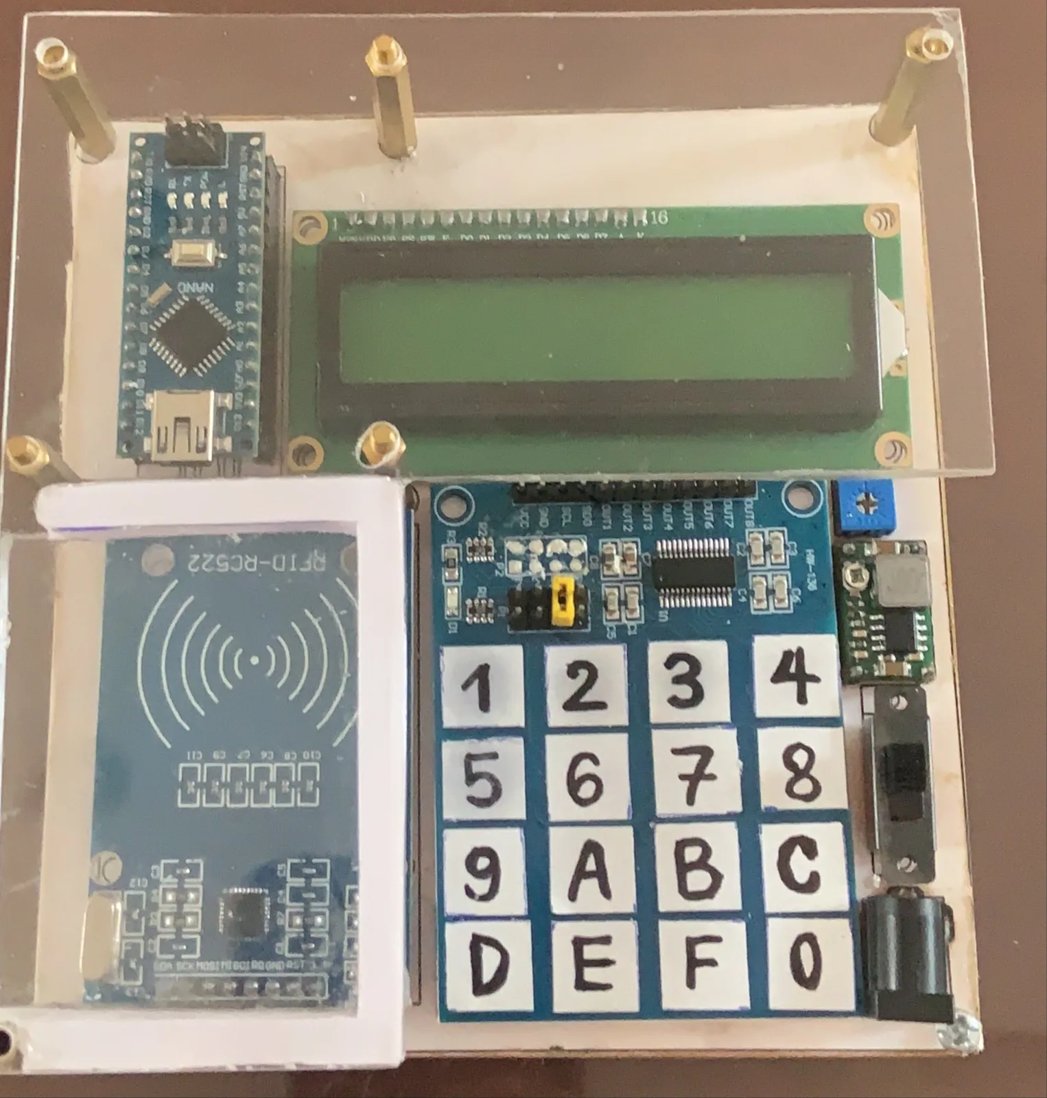
The second was a standalone 13.56 MHz card reader and writer, to read a card’s ID and copy it to a blank card.
How it works
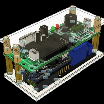
Each device is an Arduino Nano with modules around it. On the lock, a 125 kHz reader tells the Nano when it reads the implant, and the Nano switches the motorcycle’s wiring with two relays. The reader and writer reads and writes 13.56 MHz cards through an RC522 module, with a keypad and an LCD. Click a block to see what it does and why.
The two devices, block by block. Blocks: Bike supply (14 V); Regulators (L7812, Mini-360); xEM reader (125 kHz); Arduino Nano (lock logic); Relays (ignition, kill circuit); DC jack (4.75 to 23 V); Keypad (16 touch keys); Arduino Nano (reader logic); LCD (16x2); RC522 (13.56 MHz reader). Bike supply to Regulators; Regulators to xEM reader, 12 V; Regulators to Arduino Nano, 5 V; xEM reader to Arduino Nano, 5 V line; Arduino Nano to Relays; DC jack to Arduino Nano; Keypad to Arduino Nano; Arduino Nano to LCD; Arduino Nano to and from RC522, SPI.
Click a labeled block to see what it does and why.
Two devices, block by block
The motorcycle lock is at the top, and the card reader and writer below it. Click a block to see what it does and why.
In this layer
- xEM reader A Dangerous Things xEM Access Controller v2, a 125 kHz reader running at 12 V, stores the allowed tags and raises a 5 V line when it reads one.
- Arduino Nano It watches the reader's line and drives the two relays and a status LED.
- Relays Two relays switch the motorcycle's wires: unlocking connects the ignition supply to the engine wire and breaks the kill circuit.
- Regulators From the bike's 14 V, an L7812 regulator makes 12 V for the reader, and a Mini-360 buck converter makes 5 V for the Nano and the relays.
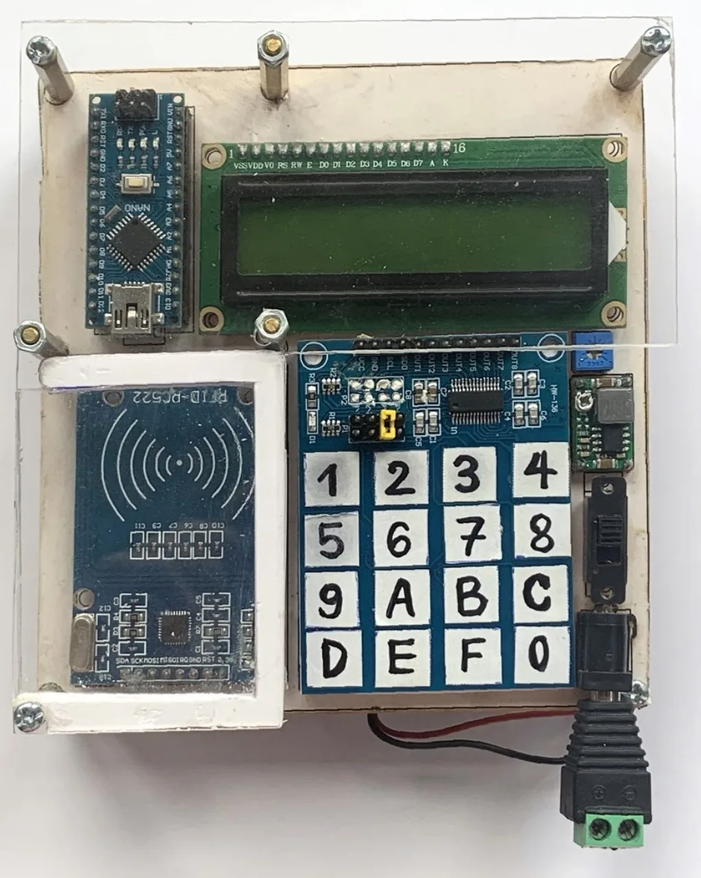
- Arduino Nano It runs the box's five modes: read a card, copy it to a blank card, write a UID typed on the keypad, reset a card, and keep a list of saved UIDs.
- RC522 A reader module that reads a card's UID, its ID number, and writes to cards.
- Keypad and LCD A TTP229 16-key touch keypad picks the mode and types UIDs, and a 16x2 character LCD shows the results.
- DC jack The box runs from 4.75 to 23 V at over 1 A, through a 5.5 × 2.1 mm DC jack.
xEM reader: the one that reaches the implant
A Dangerous Things xEM Access Controller v2, a 125 kHz reader running at 12 V, stores the allowed tags and raises a 5 V line when it reads one.
The first reader
Prototypes 1 and 2 used an RDM6300, which runs on 5 V and “would not generate enough power to pick up the implanted RFID tag”. From the third prototype on, the lock uses the xEM reader.
Range
No measurement of the read range is on record.
Arduino Nano: the lock's logic
It watches the reader's line and drives the two relays and a status LED.
Reading the line
It reads the line on an analog pin and takes anything over 900 counts, about 4.4 V, as the reader's signal.
The LED
A green LED blinks while locked and stays on while unlocked. A 2N3904 transistor drives it from 12 V.
Relays: the motorcycle's wiring
Two relays switch the motorcycle's wires: unlocking connects the ignition supply to the engine wire and breaks the kill circuit.
On the board
From the fourth prototype on, I modified the two-relay module to solder straight onto the board.
Regulators: 12 V and 5 V from the bike
From the bike's 14 V, an L7812 regulator makes 12 V for the reader, and a Mini-360 buck converter makes 5 V for the Nano and the relays.
My spec gives the reason for the buck converter, a switching regulator that steps a voltage down, in one word: “Cooler”.
Hot, then cooler
The fourth prototype made its 5 V with an L7805 linear regulator and ran hot. The fifth replaced it with the Mini-360 and ran cooler.
Idle current
No measurement of the idle draw is on record.
Arduino Nano: the reader and writer's logic
It runs the box's five modes: read a card, copy it to a blank card, write a UID typed on the keypad, reset a card, and keep a list of saved UIDs.
Firmware
979 lines of Arduino C++, built on the MFRC522 library for the reader.
RC522: the 13.56 MHz reader
A reader module that reads a card's UID, its ID number, and writes to cards.
What it can copy
It can write a UID only to a card whose block 0, the block that holds the UID, can be changed. For each card it reads, the box says whether the card can be copied.
Keypad and LCD: the controls
A TTP229 16-key touch keypad picks the mode and types UIDs, and a 16x2 character LCD shows the results.
The keypad
The Nano reads all 16 keys on two pins, as a clock and a data line.
The LCD
A 10 kΩ trimmer sets its contrast.
DC jack: power for the box
The box runs from 4.75 to 23 V at over 1 A, through a 5.5 × 2.1 mm DC jack.
Also on the supply
A Mini360 buck converter makes the Nano's 5 V, and a slide switch turns the box on.
Bring-up
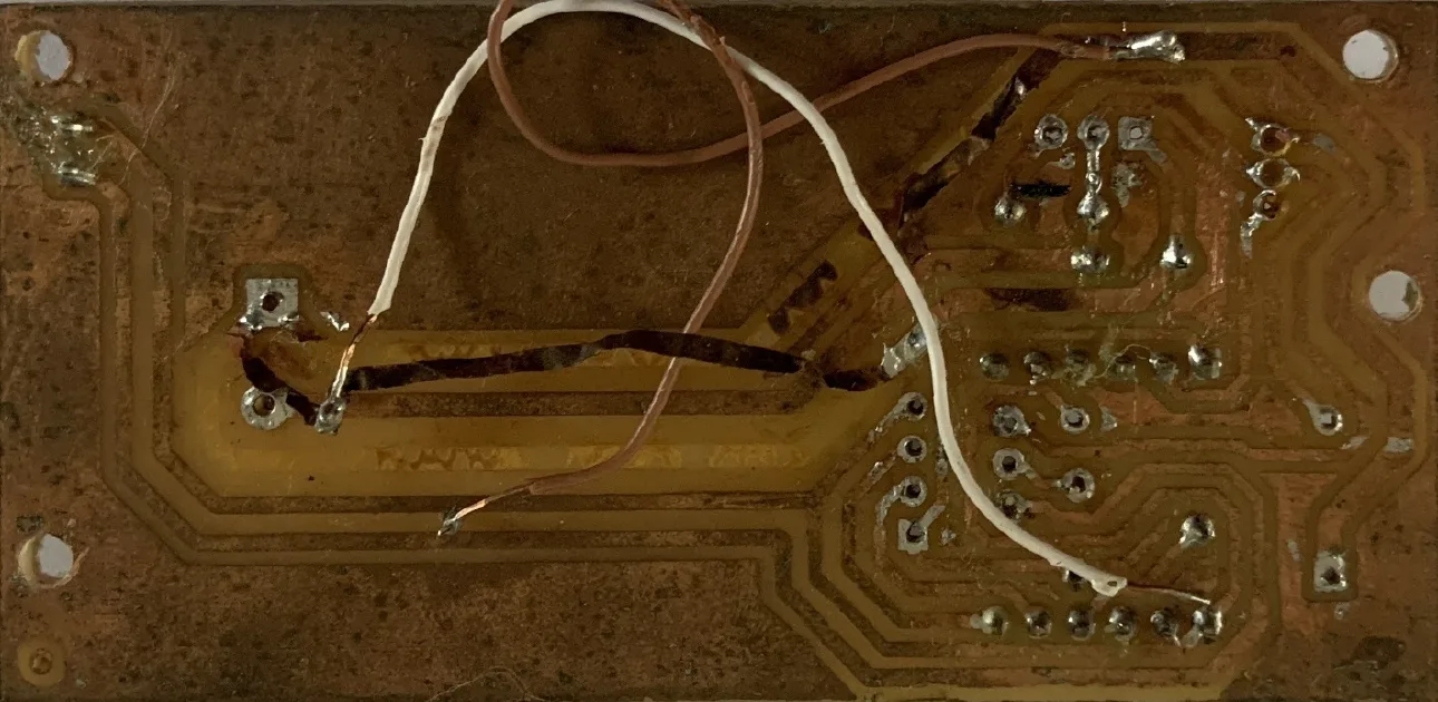
At least seven prototypes, all on single-sided boards I etched at home, got the lock onto the motorcycle and then made it cooler and smaller. The reader changed on the third, and the fourth was the first to work on the motorcycle.
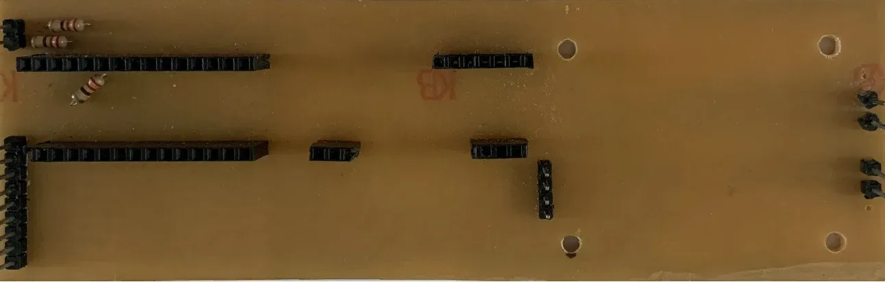
RDM6300 reader, long board
The 5 V reader could not pick up the implant, and the board was too long.
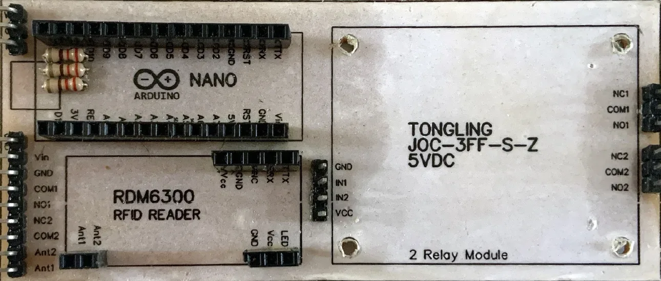
Parts re-placed
Reader still could not easily detect the implant; ten loose relay wires.
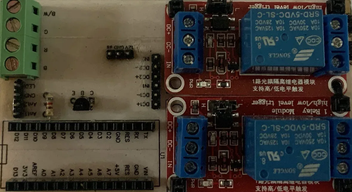
xEM reader at 12 V
It picks up the implant easily, but 14 V was unregulated and the relays were wired.
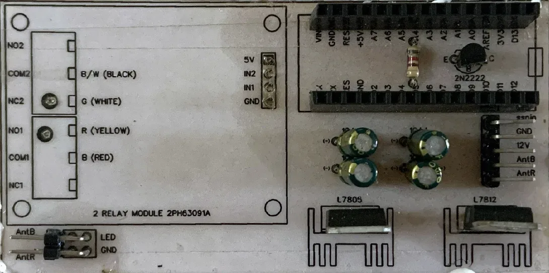
L7805 and L7812 added
First to work on the motorcycle, though hot and bulky.
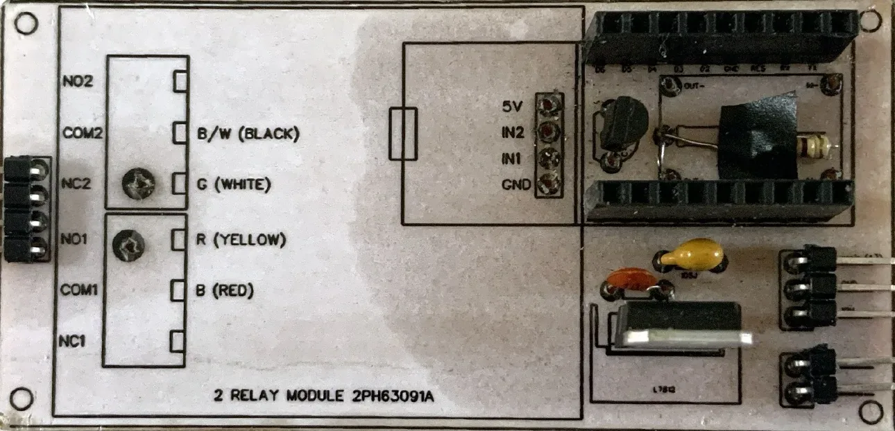
Buck converter replaces L7805
Cooler, but the 14 V trace was too thin and busted.
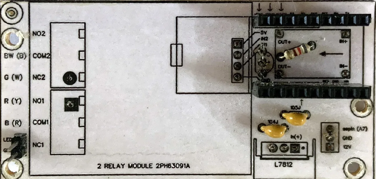
Wider traces, smaller board
Worked well until a test shorted 14 V to ground and burned a trace.
Credit
I designed and built both. A supervisor worked with me on the lock. It was a personal project, not paid work.