ROV X16 electrical stack
Purdue IEEE ROV
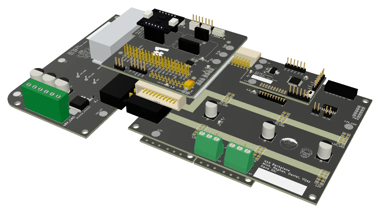
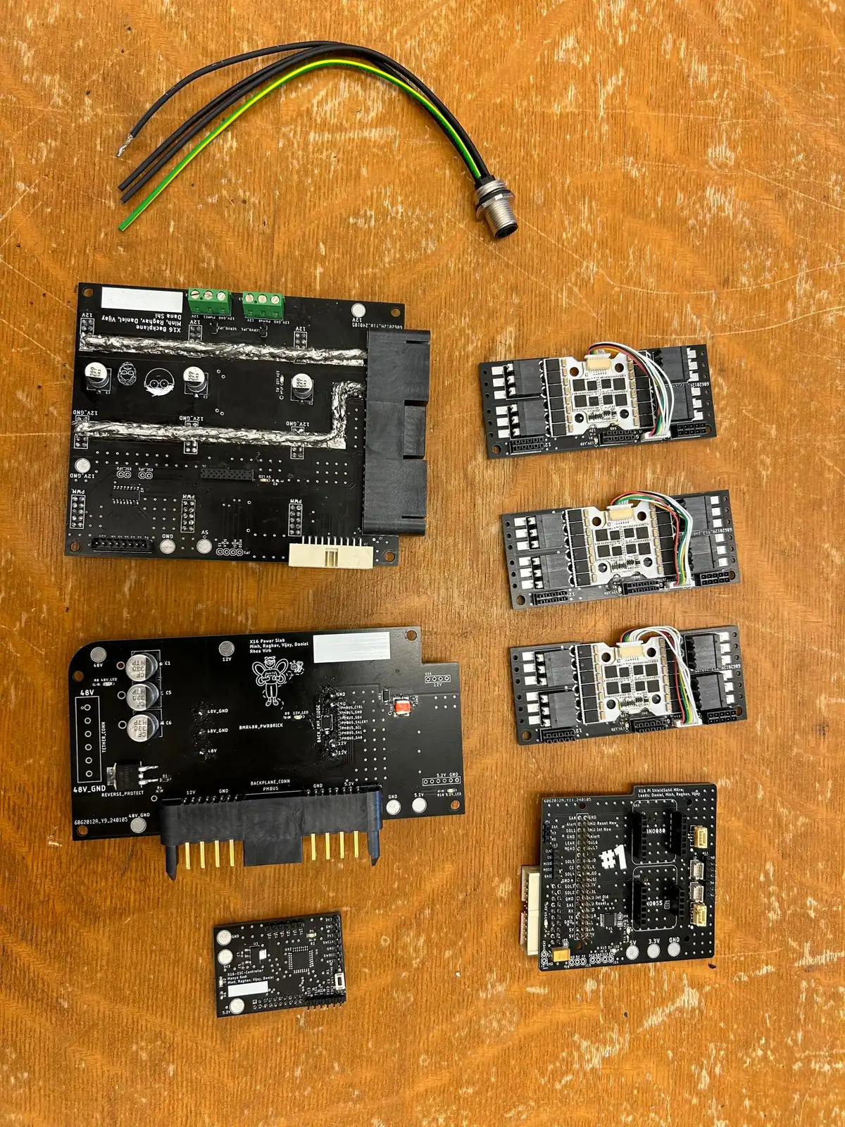
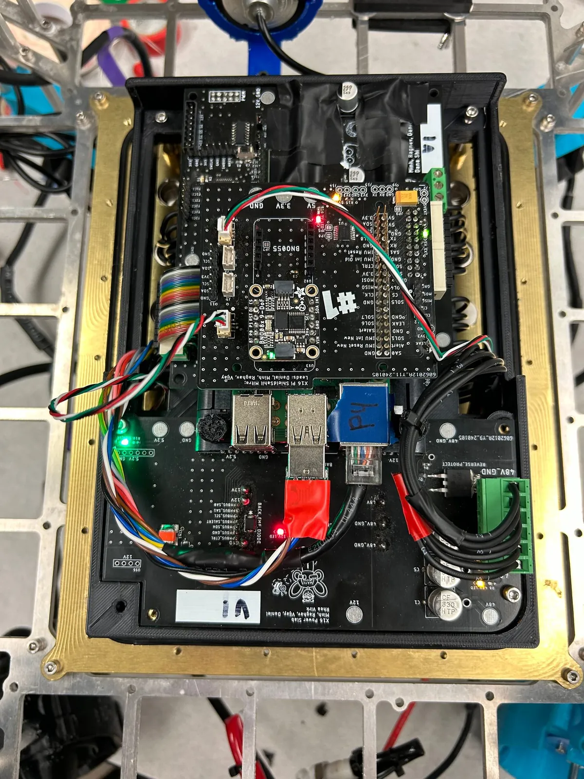
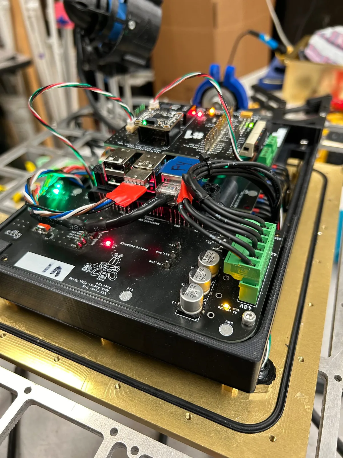
The electrical stack of the team's 2023-24 vehicle: five boards, down from seven. The team won the Explorer class Technical Documentation Award at the 2024 World Championship.
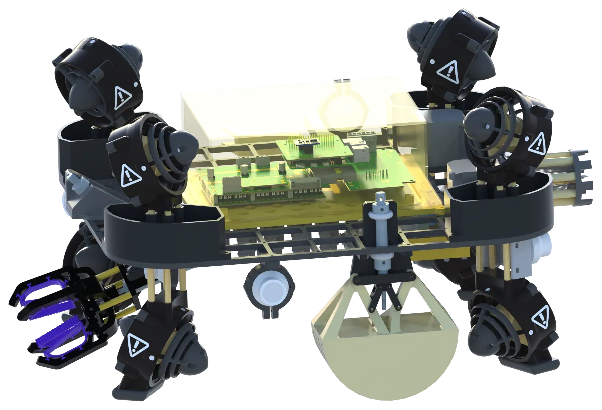
The problem
X16 had to fix what failed on X15. The 2024 report names “embedded communication issues between microcontrollers, high camera latency, and unreliable connectors”, and boards “not mounted securely”.
The job was the same: drive eight thrusters, four cameras, the solenoid valves and a Raspberry Pi 4B from one tether. The surface supply gives 48 V at up to 30 A. The X15 post-mortem asked for fewer boards and earlier testing, because a late stack had left the other teams nothing realistic to test.
How it works
The stack turns the tether’s 48 V into 12 V and 5.2 V, and passes the Pi’s commands to the thrusters.
Power enters through a 25 A fuse to the Power Slab, which carries the power brick and makes both rails. The Backplane passes power and signals to the Pi Shield, the ESC Controller and two ESC adapters. Click a board to see what it does and the choices behind it.
The X16 stack, board by board. Blocks: Tether (from the control box); Tether fuse (25 A); Power Slab v2 (LM2679 buck); Power brick (BMR480); Backplane (carries power and signals between the boards); Solenoid valves; Servo terminals; Pi Shield (on the Raspberry Pi 4B); ESC Controller (own 3.3 V LDO); 2 ESC adapters (a 4-in-1 ESC on each); 8 thrusters. Tether to Tether fuse, 48 V; Tether fuse to Power Slab v2; Power Slab v2 to Power brick, 48 V; Power brick to Power Slab v2, 12 V; Power Slab v2 to Backplane, 12 V, 5.2 V on one connector; Backplane to Solenoid valves, 12 V; Backplane to Servo terminals, 12 V; Backplane to Pi Shield, 5.2 V; Backplane to ESC Controller, 5.2 V; Backplane to 2 ESC adapters, 12 V; 2 ESC adapters to 8 thrusters; Pi Shield to ESC Controller, SPI; ESC Controller to 2 ESC adapters, PWM.
Click a labeled block to see what it does and why.
The stack, board by board
Power comes down from the tether at the top, and the Backplane passes it to the boards below. Teammates drew the boards; click one to see what it does and the choices behind it.
In this layer
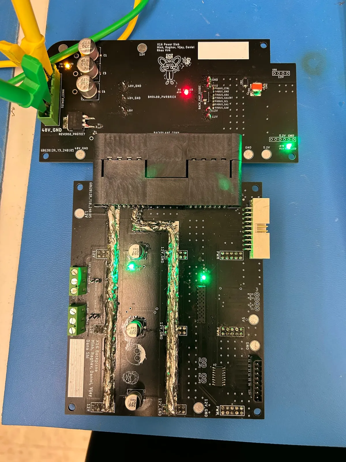
- Power Slab v2 Carries the power brick, a DC-DC converter module that makes 12 V from 48 V, and makes 5.2 V with a buck converter, a switching regulator that steps voltage down.
- Backplane Carries power and signals between the boards, drives the solenoid valves with a ULN2003 driver chip, and feeds 12 V to the servo terminals.
- Pi Shield Joins the Raspberry Pi 4B to the stack, with two IMUs (motion sensors) and an INA260 power monitor on the Pi's 5 V supply.
- ESC Controller An STM32F042 microcontroller that takes the Pi's commands over SPI and sends PWM pulses to the ESCs.
- 2 ESC adapters Each adapter carries a 4-in-1 ESC, an electronic speed controller, that drives four thrusters from 12 V. The team built three; the vehicle's eight thrusters use two.
Power Slab: 48 V to 12 V and 5.2 V
Carries the power brick, a DC-DC converter module that makes 12 V from 48 V, and makes 5.2 V with a buck converter, a switching regulator that steps voltage down.
We merged X15's two power boards into the Power Slab, as the X15 post-mortem asked, to reduce “the electrical stack's size and weight”.
What it cost
Modularity. An alumni reviewer warned: “If either board fails, you lose both of them now.”
No 3.3 V rail
The slab makes no 3.3 V. Each board that needs 3.3 V makes its own with a linear regulator.
The brick
A Flex BMR4800116/005, a model with PMBus status lines. They run through the Backplane and the Pi Shield to the Pi. The Pi's software could read them, but we made little use of it.
Three seasons of power boards
Blocks: Distribution and 2 brick boards (two bricks), in X14: 12 boards; X14 Conversion (LM2678, AZ1117), in X14: 12 boards; Brickstribution (one brick), in X15: 7 boards; X15 Conversion (LM2679, AZ1117), in X15: 7 boards; Power Slab v2 (one brick, LM2679 buck; 3.3 V made on the boards that use it), in X16: 5 boards.
- Distribution and 2 brick boards to Brickstribution.
- X14 Conversion to X15 Conversion.
- Brickstribution to Power Slab v2.
- X15 Conversion to Power Slab v2.
Backplane: power and signals between the boards
Carries power and signals between the boards, drives the solenoid valves with a ULN2003 driver chip, and feeds 12 V to the servo terminals.
We chose one ET60 connector to the Power Slab, for power and logic, over X15's power connector plus a ribbon cable, which “increases potential failure points”.
One connector
The ET60 carries 12 V, 5.2 V and the brick's status lines. It scored 24 of 25 on our decision matrix, against 18 for the old pair.
At bring-up
The 5 V and ground pins between the Backplane and the Power Slab were swapped. The fix is not recorded.
Pi Shield: the Pi's link to the stack
Joins the Raspberry Pi 4B to the stack, with two IMUs (motion sensors) and an INA260 power monitor on the Pi's 5 V supply.
X15's CAN parts are gone: the Pi now talks to the ESC Controller over SPI.
Mounting
The Pi and its Shield sat on their own 3D-printed scaffold.
Data path
Blocks: 4 USB cameras; Raspberry Pi 4B; Power brick; ULN2003 driver (on the Backplane); Pi Shield; IMUs, power monitor (BNO055, BNO080, INA260); 4 solenoid valves; ESC Controller (STM32F042); Servo; 2 ESC adapters (a 4-in-1 ESC on each).
- Raspberry Pi 4B to and from 4 USB cameras: USB, through a hub.
- Power brick to Raspberry Pi 4B: PMBus.
- Raspberry Pi 4B to and from Pi Shield.
- Pi Shield to and from IMUs, power monitor: I2C.
- Pi Shield to ULN2003 driver: GPIO.
- ULN2003 driver to 4 solenoid valves.
- Pi Shield to and from ESC Controller: SPI, 500 kHz.
- ESC Controller to 2 ESC adapters: 8 PWM, 500 Hz.
- ESC Controller to Servo: 50 Hz PWM.
ESC Controller: SPI in, PWM out
An STM32F042 microcontroller that takes the Pi's commands over SPI and sends PWM pulses to the ESCs.
We chose SPI over CAN, UART and I2C on a decision matrix: it had been “proven as a temporary fix last year”, and it needed no extra chips.
At bring-up
Its STM32 burned out as soon as the whole stack was powered. A connector on the ESC adapter was reversed and put 12 V on its pins. The fix was a reversed JST cable on the adapter.
Then the link
The controller then “wasn't communicating with the Pi”. The team traced it from the wiring to the Pi Shield's output on an oscilloscope, then to the controller under a debugger. The fix was in firmware.
Numbers
| Link | Score of 20 |
|---|---|
| SPI (chosen) | 17 |
| UART | 15 |
| CAN | 14 |
| I2C | 14 |
ESC adapters: four thrusters each
Each adapter carries a 4-in-1 ESC, an electronic speed controller, that drives four thrusters from 12 V. The team built three; the vehicle's eight thrusters use two.
Its connector to the Backplane is keyed, so it fits only one way.
At bring-up
The cutout for the ESC was too small, so the team filed the boards down.
Design process
My co-lead, Raghav Kumar, and I set the season’s goals and presented them at the alumni design review on 28 October 2023. First, fix X15’s “Thruster Control & Cameras”. Then merge boards, and make them modular, with “Better connectors, Less wires between boards”. We also put early testing first, “to avoid last year problem with electrical debugging”.
The reviewers questioned the merge, and suggested mounting the ESCs above the Backplane. The team lead of the time kept both as planned. Two changes did come from the review: a keyed connector on the ESC adapter, since X15’s misaligned one “caused 12V and GND to be shorted”, and a new Pi Shield to Backplane connector.
A board-by-board review followed on 18 November, and the manufacturing files date from 27 December to 4 January.
Three choices are in their boards above: SPI to the ESC Controller, the Power Slab merge and one connector to the Backplane.
Testing and competition
The boards were soldered in January 2024, small parts first, and the vehicle’s maiden voyage was on 29 February. Putting the stack together found three faults, each told in its board above.
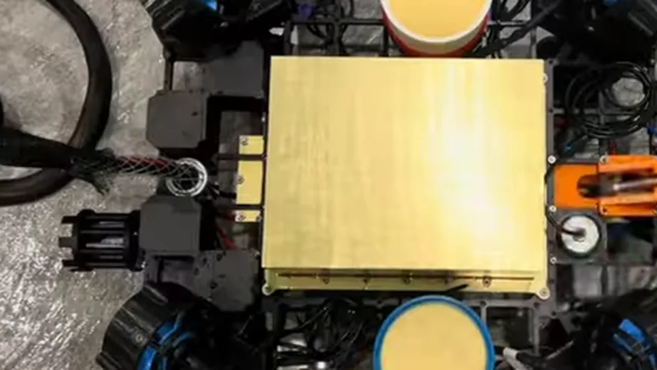
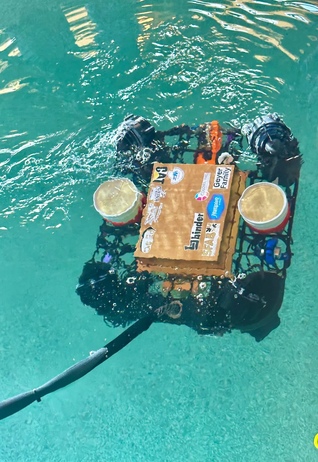
The qualification video, posted on 13 May 2024, shows the safety checks and a pool run of about eight minutes. It never shows the electronics, which sit inside the gold Power Box.
Results
The team placed 11th of 29 in the Explorer class at the 2024 MATE ROV World Championship (score sheet). It also won the class’s Technical Documentation Award (MATE’s awards page).
Our hand-off notes call the stack stable at the season’s end: “No ESC Burned”, “No Power Related Issues”. No rail or current was measured on record.
They also hand on four open problems: unreliable cameras, thrusters that “lag out”, a Pi and brick that heat up, and about 100 A of peak current, called “not safe”. As far as I know, nothing was done about the current that season.
Explore the boards
Teammates drew these five boards, shown here to one scale. Pick one to pan, zoom and click any part in three linked views.
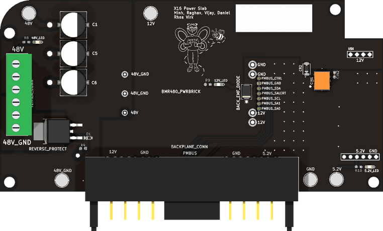 Power Slab v248 V to 12 V through the brick, then 12 V to 5.2 V with a buck converter.
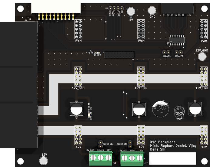 BackplaneCarries power and signals between the boards and drives the solenoids.
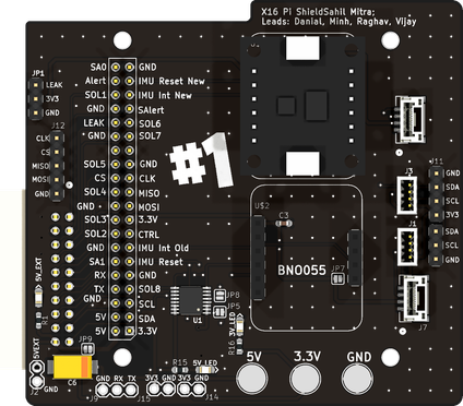 Pi ShieldConnects the Pi to the stack, with two IMUs and a power monitor.
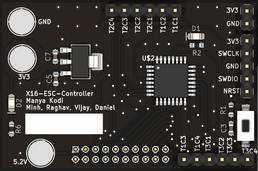 ESC ControllerAn STM32F042 that takes SPI from the Pi and drives the ESCs with PWM.
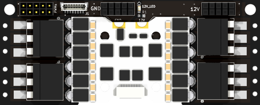 ESC AdapterCarries one 4-in-1 ESC for four thrusters. Two flew.
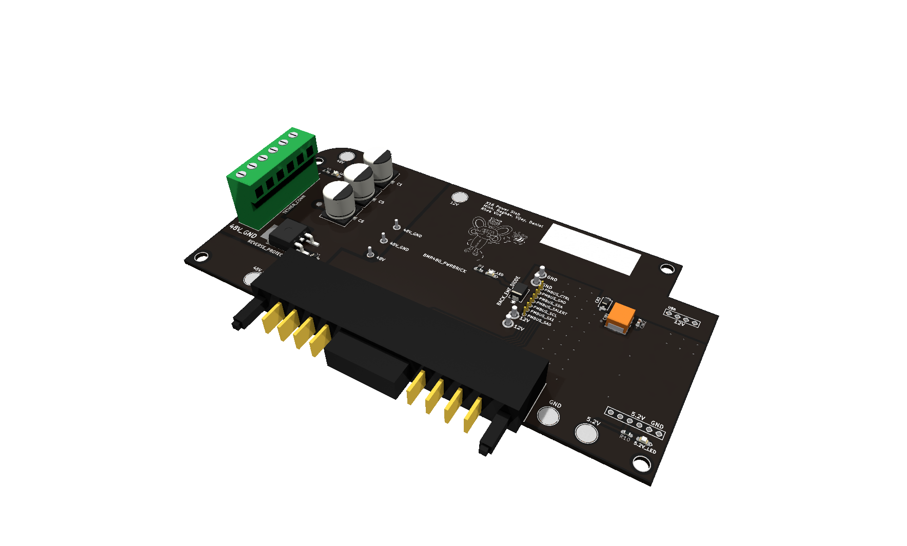
Power Slab v2: 3D model, 0.3 MB.
Credit
I was Electrical Co-Lead: with my co-lead I set the goals and stack changes, led the electrical team and wrote most of the hand-off. Teammates drew the boards and wrote the thruster firmware.
Technical report
The Purdue ROV 2024 Technical Report won the Explorer Class Technical Documentation Award in the MATE 2024 Competition. It covers the whole vehicle, the electrical stack included.