ROV X15 electrical stack
Purdue IEEE ROV
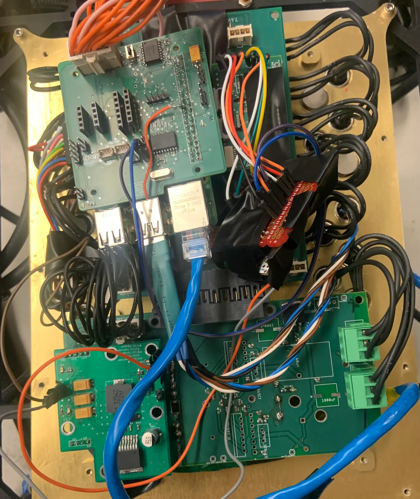
The electrical stack of the team's 2022-23 underwater vehicle, planned at seven boards where the last vehicle had twelve. The vehicle placed 6th of 23 at the 2023 MATE World Championship.
The problem
X15 had to drive eight thrusters, a Raspberry Pi 4 and the pneumatic valves from one tether. The surface supply gives 48 V at up to 30 A.
X14, the year before, did it with twelve boards and two power bricks. Its electronics were “hard to maintain due to the narrow space surrounding the electronics”, and the bricks’ status data never reached the Pi.
The season ran from board sizing in September 2022 to the World Championship in June 2023. Teammates drew the boards. My job was the plan they drew to, and the build that followed.
How it works
The stack turns the tether’s 48 V into the low-voltage rails the boards need and carries the Pi’s commands to the thrusters.
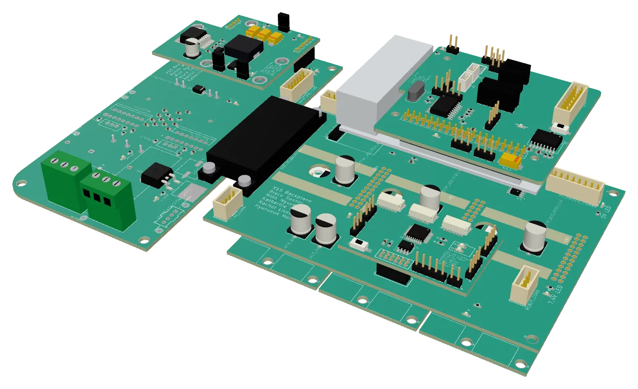
Power enters through a 25 A fuse to Brickstribution, which carries the power brick, and the Power Conversion board on top of it makes the low-voltage rails. The Backplane passes power and signals to the Pi Shield, the ESC controller and three ESC adapters. Click a board to see what it does and the choices behind it.
The X15 stack, board by board. Blocks: Tether (from the surface); In-line fuse (25 A); Brickstribution (carries the power brick); Power brick (BMR4800106); Power Conversion (buck and LDO); Backplane (routes power and signals between the boards); Solenoid valves; Pi Shield (on the Raspberry Pi 4); ESC controller; 3 ESC adapters (a 4-in-1 ESC on each); 8 thrusters. Tether to In-line fuse, 48 V; In-line fuse to Brickstribution; Brickstribution to Power brick, 48 V; Power brick to Brickstribution, 12 V; Brickstribution to Power Conversion, 12 V; Power Conversion to Brickstribution, 5.2 V, 3.3 V; Brickstribution to Backplane, 12 V, 5.2 V, 3.3 V on two connectors; Backplane to Solenoid valves, 12 V; Backplane to Pi Shield, 5.2 V; Backplane to ESC controller, 3.3 V; Backplane to 3 ESC adapters, 12 V; 3 ESC adapters to 8 thrusters, 3-phase; Pi Shield to ESC controller, SPI; ESC controller to 3 ESC adapters, PWM.
Click a labeled block to see what it does and why.
The stack, board by board
Power comes down from the tether at the top, and the Backplane passes it to the boards below. Teammates drew the boards; click one to see what it does and the choices behind it.
In this layer
- Brickstribution Takes the tether's 48 V and carries the power brick, a DC-DC converter module that makes 12 V from 48 V for the stack.
- Power Conversion Sits on top of Brickstribution and makes 5.2 V with a buck converter, a switching regulator that steps voltage down, and 3.3 V with an LDO, a linear regulator.
- Backplane Routes power and signals between the boards, and drives the solenoid valves with a ULN2003 driver chip.
- Pi Shield Powers the Raspberry Pi 4 and joins it to the stack, and to a depth sensor and an IMU (a motion sensor) over I2C.
- ESC controller Turns the Pi's commands into the PWM pulses the ESCs read.
- 3 ESC adapters Each adapter carries a Lumenier 4-in-1 ESC, an electronic speed controller that turns 12 V into three-phase drive for four thruster motors. The stack takes three adapters; the vehicle's eight thrusters use two.
Brickstribution: 48 V in, 12 V out
Takes the tether's 48 V and carries the power brick, a DC-DC converter module that makes 12 V from 48 V for the stack.
It merged X14's Distribution board and two brick boards into one, the challenge I had set it for the year.
One brick, not two
We chose one 1300 W brick over X14's two 600 W bricks. It cost the brick's status data: the model we ordered has no digital interface, so the brick could not report to the Pi.
At bring-up
Its documentation lists an inductor placed on the wrong side of the board, and a zener diode that tripped the supply when fitted backwards across 12 V.
Power Conversion: 5.2 V and 3.3 V
Sits on top of Brickstribution and makes 5.2 V with a buck converter, a switching regulator that steps voltage down, and 3.3 V with an LDO, a linear regulator.
A teammate drew it from my X14 Conversion board, on the same outline.
What changed
It moved to the LM2679 buck, the in-stock successor my X14 notes named, and added LEDs for 12 V, 5.2 V and 3.3 V. Its designer picked the AZ1117 regulator on my recommendation.
Backplane: power and signals between the boards
Routes power and signals between the boards, and drives the solenoid valves with a ULN2003 driver chip.
Its designer set the rule that “No logic signal should cross the 12V power line”.
Changes from X14
The solenoid driver moved here from the Pi Shield, and a 7.4 V line was added for a servo arm.
Pi Shield: the Pi's link to the stack
Powers the Raspberry Pi 4 and joins it to the stack, and to a depth sensor and an IMU (a motion sensor) over I2C.
As drawn and as flown
It was drawn with a HI-3110 CAN controller to reach the ESC controller. As flown, it sent SPI to the controller instead.
In the water
The post-mortem logs an “Inconsistent LED (connector of pi shield is loose)”.
Data path, as flown
Blocks: Surface; Raspberry Pi 4; Pi Shield; Depth sensor, IMU; ULN2003 driver (on the Backplane); Solenoid valves; ESC controller (Nucleo32 adapter); 3 Lumenier ESCs (4-in-1).
- Surface to and from Raspberry Pi 4: Ethernet, shielded CAT6.
- Raspberry Pi 4 to and from Pi Shield: I2C, SPI, GPIO.
- Pi Shield to and from Depth sensor, IMU: I2C.
- Pi Shield to ULN2003 driver: 4 GPIO.
- ULN2003 driver to Solenoid valves.
- Pi Shield to ESC controller: SPI.
- ESC controller to 3 Lumenier ESCs: 10 PWM.
ESC controller: commands to PWM
Turns the Pi's commands into the PWM pulses the ESCs read.
Version 3 puts all three ESC slots on one STM32 board, where X14 had three controller boards.
CAN to SPI
CAN to the controller did not work; the February notes record “some unknown error”. We chose SPI over CAN, and the report gives the reason: the stack had “only a single master, the Raspberry Pi, and a single slave”, so “SPI offered simpler integration”.
What it cost
As a stopgap the team wired SPI to a Nucleo32 board, off the board files. The competition presentation calls it “Very unreliable because of jumpers”.
CAN as designed, SPI as flown
Blocks: Pi Shield (HI-3110 CAN controller); ESC Controller v3 (STM32F042, CAN transceiver); Nucleo32 adapter (as flown); Lumenier ESCs.
- Pi Shield to and from ESC Controller v3: CAN_H, CAN_L via the Backplane (dashed).
- Pi Shield to Nucleo32 adapter: SPI.
- ESC Controller v3 to Lumenier ESCs: PWM (dashed).
- Nucleo32 adapter to Lumenier ESCs: 10 PWM.
ESC adapters: 12 V to the thrusters
Each adapter carries a Lumenier 4-in-1 ESC, an electronic speed controller that turns 12 V into three-phase drive for four thruster motors. The stack takes three adapters; the vehicle's eight thrusters use two.
Its designer kept to Samtec connectors, “so we could get free connectors”.
In the water
The thruster connectors came off the adapters, and the wires were soldered straight to the boards. The post-mortem: “Esc is soldered, not detachable”.
Design process
The season ran from goals in September 2022 to a list for X16.
At the start I set each board a challenge for the year, in my onboarding deck for new members. Distribution’s was “Merge with Bricks into 1 board”. On 15 September 2022 we drew the box layout: two sub-stacks in a 6.5 × 9 in box, so boards that were often removed stayed within reach.
Each board owner presented a schematic and layout to alumni reviewers. A check before ordering, dated 21 December 2022, listed faults on each board, such as “vias not enough”.
The season’s two big changes are in their boards above: the Brickstribution merge, and the switch from CAN to SPI.
The post-mortem handed X16 its list: “Merge power conversion and brickstribution”, “Optional to kill 7.4V” and “Drop CAN, switch to spi”.
Testing and competition
New members soldered their own boards in early 2023, under the leads’ supervision. Each board passed five checks before it joined the stack: a visual check, continuity, the power LED, rail voltages and current draw. The faults the build found are in their boards above.
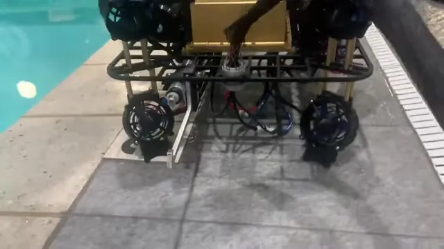
The qualification video, posted on 20 May 2023, shows the safety checks and a pool run of nearly 15 minutes. It never shows the electronics, which sit inside the gold Power Box.
Results
The vehicle placed 6th of 23 in the Explorer class at the 2023 MATE ROV World Championship (score sheet).
The only measured rails are Brickstribution’s bench readings. The brick gave about 11.3 V against its datasheet’s 12 V set point, and the 7.4 V servo rail about 7.6 V. No load test is on record either, so 1300 W and 25 A are ratings.
The post-mortem lists what still failed: “Unstable esc, can’t go max thrust”. The stack was late enough that “neither mechanical nor software could run realistic tests”.
Explore the boards
Teammates drew these six boards, shown here to one scale. Pick one to pan, zoom and click any part in three linked views.
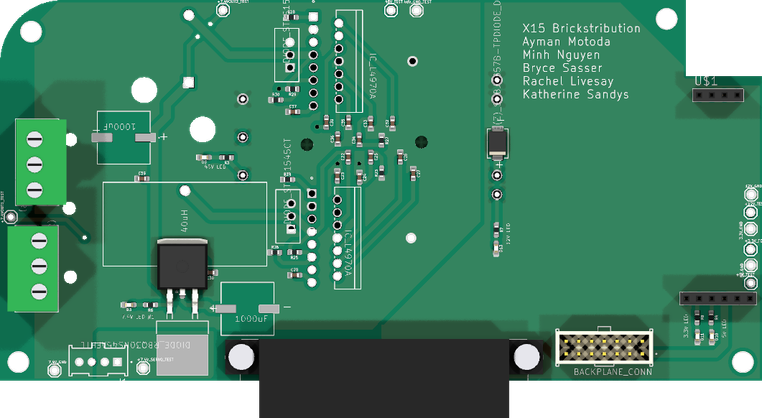 BrickstributionTakes the 48 V tether, carries the power brick and sends 12 V to the stack.
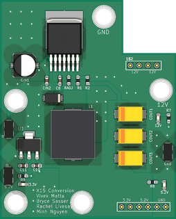 Power Conversion12 V to 5.2 V with a buck converter, and 3.3 V with an LDO.
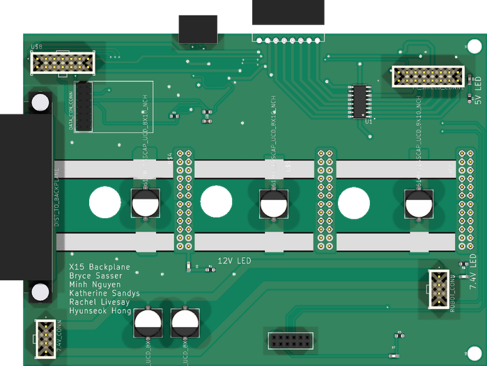 BackplaneRoutes power and signals between the boards and drives the solenoids.
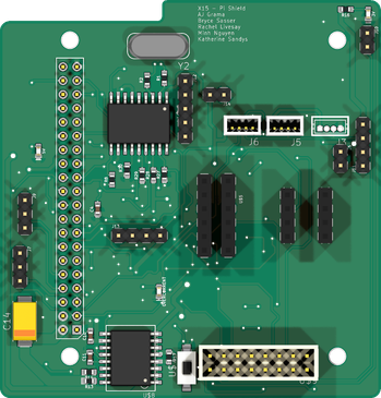 Pi ShieldPowers the Pi and connects its sensors.
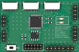 ESC Controller v3One STM32 board for all three ESCs, designed for CAN.
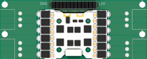 ESC AdapterCarries a Lumenier 4-in-1 ESC for four thrusters. Three were built; two carry the eight thrusters.
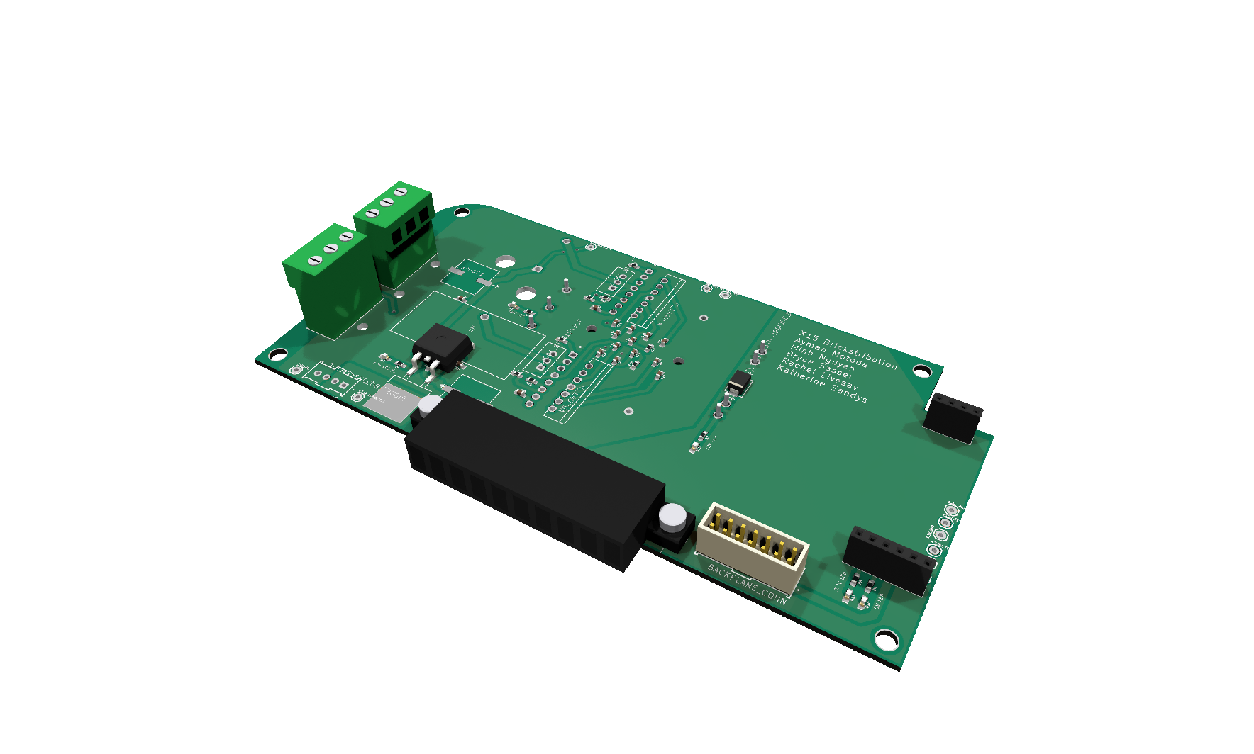
Brickstribution: 3D model, 0.3 MB.
Credit
I was Electrical PCB Head: I set the boards’ goals, advised their designers, and ran manufacturing, soldering training, box layout and debugging. Teammates drew the boards, and the software team wrote the firmware.