SoCET CAN-bus shield
Purdue, SoCET VIP team
A two-layer shield that gives the AFTx06 chip's board a CAN bus port. It was graded 100/100, and I used it to teach new members board design.
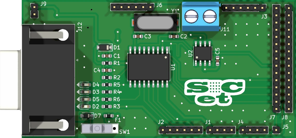
- OBD-II DB9CAN and 12 V
- LD1117, back12 V to 5 V
- Screw terminalCANH, CANL
- Shield headersIO7 to IO37
- MCP2515CAN controller
- MCP2551CAN transceiver
76 × 38.3 mm2 copper layers40 footprints67 nets87 vias
- Power
- Logic
- I/O
The problem
SoCET’s AFTx06 chip “has been taped out and developed but has not been tested with real life application.” The team’s goal for it was a shield “that can communicate with the CAN signal of mainly autonomous vehicles”. CAN is the two-wire bus that links the control units in a car.
The shield had to plug into the team’s shield platform for the AFTx06 board, whose header pinout was a fixed template. It had to take CAN and 12 V in through a DB9 connector wired for OBD-II, the diagnostic port on cars, and run its parts on 5 V.
How it works
The shield turns the chip board’s SPI, a four-wire serial bus, into CAN, and can draw its power from the car. An MCP2515 controller builds the CAN messages, and an MCP2551 transceiver puts them on the bus’s two wires. Click a block to see what it does and why.
CAN-bus shield, block by block. Blocks: Screw terminal (CANH, CANL); OBD-II DB9 (CAN and 12 V); MCP2551 (CAN transceiver); MCP2515 (CAN controller); Shield headers (AFTx06 board); Fuse (and switch); LD1117 (12 V to 5 V). OBD-II DB9 to and from MCP2551, CANH, CANL; Screw terminal to and from MCP2551; MCP2551 to and from MCP2515, TX, RX; MCP2515 to and from Shield headers, SPI; OBD-II DB9 to Fuse, 12 V; Fuse to LD1117; LD1117 to Shield headers, 5 V.
Click a labeled block to see what it does and why.
The shield, block by block
CAN and 12 V come in from the car at the left, and the chip's board plugs in at the right. Click a block to see what it does and why.
In this layer
- OBD-II DB9 A DB9 connector wired for OBD-II, the diagnostic port on cars, brings in the CAN bus and 12 V.
- MCP2551 The CAN transceiver turns the controller's TX and RX into the voltages on the bus's two wires, CANH and CANL.
- MCP2515 The CAN controller takes SPI, a four-wire serial bus, from the chip's board and builds the CAN messages.
- LD1117 A linear regulator on the back of the board turns the car's 12 V into the 5 V the shield's parts run on.
- Shield headers Two 1x15 headers mate with the AFTx06 chip's board, with separate headers for UART, SPI and power.
OBD-II DB9: CAN and 12 V from the car
A DB9 connector wired for OBD-II, the diagnostic port on cars, brings in the CAN bus and 12 V.
Pin-out
CANH on pin 3, CANL on pin 5, 12 V on pin 9 and ground on pin 2.
Screw terminal
CANH and CANL also go to a two-pin screw terminal.
MCP2551: onto the bus
The CAN transceiver turns the controller's TX and RX into the voltages on the bus's two wires, CANH and CANL.
CANH and CANL are a differential pair, so I routed them together and matched their lengths: noise then lands on both wires alike, and the transceiver rejects it. My notes put it as CAN signals being “easily prone with noises from the environment”.
Matched lengths
CANH and CANL, the bus pair, differ by 0.01 mm. I matched TXCAN and RXCAN, between the controller and the transceiver, to 0.03 mm too, which is more care than a CAN bit rate needs.
Numbers
| Line | Length |
|---|---|
| CANH | 65.65 mm |
| CANL | 65.66 mm |
| TXCAN | 46.50 mm |
| RXCAN | 46.53 mm |
MCP2515: SPI in, CAN out
The CAN controller takes SPI, a four-wire serial bus, from the chip's board and builds the CAN messages.
The team chose the MCP2515 and MCP2551 because they were on hand on campus and we had prototyped with them.
Clock and reset
An 8 MHz crystal clocks it. The controller must reset at start-up, so an RC network on its reset line, 6.3 kΩ and 100 pF (a 0.63 µs time constant), holds it in reset as the supply comes up.
LD1117: the car's 12 V to 5 V
A linear regulator on the back of the board turns the car's 12 V into the 5 V the shield's parts run on.
The DB9 brings the car's 12 V, and the shield's parts run on 5 V.
The path
The 12 V passes a diode, the slide switch and a 1.5 A fuse before the regulator.
Joining the supplies
I joined the two supplies “after converting to 5V”: the regulator's 5 V meets the board's 5 V through a second diode.
Shield headers: onto the AFTx06 board
Two 1x15 headers mate with the AFTx06 chip's board, with separate headers for UART, SPI and power.
Indicators
Four LEDs serve as indicators.
Design decisions
Both choices deal with what comes in from the car: noise on the CAN lines, and 12 V on the power pin. Each is in its block above: the transceiver and the regulator.
Results
The shield was not built. The design was graded 100/100, with full marks on power supply, main IC, routing, testing capabilities, neatness, placement, layers and grounding. I finished it early and used it to show new members of the PCB team a complete schematic and layout. No test of the shield is on record, so nothing on it was measured.
Explore the board
Pan, zoom and click any part. The schematic opens on the CAN sheet.
Loading the board layout.
Loading the schematic.
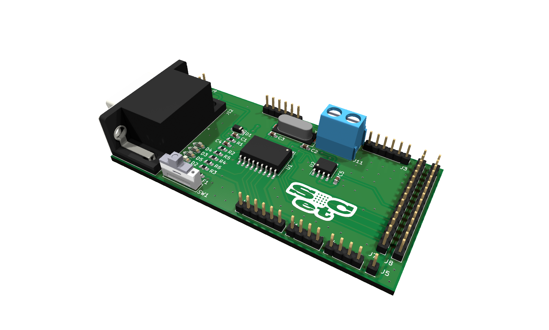
Credit
I designed the shield on my own, checking requirements with the PCB team lead, who set up the shield template.